The greatest pleasure of using a synthesizer is
being able to listen to actual sounds that you create from your imagination. A patching
system is something that was thought up to infinitely expand the possibilities of creating
your own sounds. Since there are input and output jacks on the front panel for all
synthesizer functions, it is possible to have completely free external control. With these
jacks available, you can use a microprocessor, another synthesizer, or even a homemade
control unit to vary each of the basic elements of sound.
Practically speaking, patching is not that
complicated. Patching means using patch cords to connect those sections of the
synthesizer. On the A100, each module (VCO, VCF, VCA, EG, S/H, LFO, MG, etc.) is
completely separate and are only provided with input and output jacks on the panel. You
think up an effect and try to recreate it on the synthesizer by connecting these jacks. In
this way you can go beyond the limitations accessible on a hard-wired synthesizer. You will have more freedom and creative
control of the sounds you produce.
Important points to remember when setting up a patch
Since the synthesizer is voltage controlled, you must be systematic
in your approach if you want a specific effect. If you don't follow the rules dictated by voltage control, either you'll get a sound you weren't looking for,
or nothing will happen at all. Therefore, keep in mind the following basic rules:
(1) Always cheek to see whether you are using the appropriate type
of voltage signal and voltage range for the sections you want to connect. This means
checking the control voltage range on the jacks of the sections you wish to use. (-2.5 to
+2.5V, 0 to +3V, etc.)
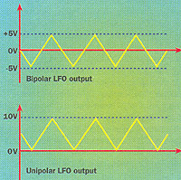 |
For example, if you connected a *bipolar LFO where the output swings between -5V
and +5V to an input "0 to +5V", the effective control range would only be from 0
to +5V; nothing would happen during the other portions of the signal.
(2) If you connect a unipolar LFO wobbling
between "0V and +10V" (or any other continuously varying control voltage) to an
input marked Gate or Trigger signals (which is a digital
ON/OFF switch-type input), the section you are trying to control will turn OFF when the
control voltage drops down to 0V and it will turn ON when the voltage goes over +5V. You
can try this by connecting the output of an unipolar LFO to the Gate IN
input on the A-140 evelope generator.
*Bipolar LFO´s wobble around zero.
Unipolar ones never go below zero. Use the wrong kind and You´ll be forever unharmonious.
|
Patching procedure
In Doepfers A100 system You can divide synthesizer modules
into three groups:
1. Audio Signals
2. Control Voltages
3. Trigger Voltages
1. Audio Signals are produced by the sound source Modules (such as VCO or NOISE),
and lie in the range from -5 V to +5 V (10 Vss). The System A-100 can also let you use
external Audio Signals (e.g. Microphone, electric Guitar, Keyboard). To interface
satisfactorily, the level of "external Audio Signals" must be brought up to the
A-100's operating level. Module A-119 (External Input), is ideal for this job,
having among other things an internal pre-amp, and two inputs of different sensitivity.
2. Control voltages
These voltages are produced by modulation sources like the LFO (-2.5 V to +2.5 V) and
ADSR (from 0 V to +8 V).
3. Trigger or Gate signals, which start a process or function, are typically from 0
V to 5V, with the trigger occurring as the leading edge of the waveform shoots up
from 0V to 5V.
These definitions of the various signals, and the distinctions between them - sound
sources and modulation sources - are right in principle, but a modular system like the
A-100 often makes a mockery of them. In a modular set-up, all of the modules produce
voltages, and can be used as control voitages or triggers, thus blurring the distinction
between the various types.
For example, the output from an LFO can be used as an audio signal, as a control
voltage for a VCF or VCA, or as a trigger signals for a sequence. It's just about true to
say that anything can be modulated by anything else, so that a modular system gives the
musician extraordinary flexibility and individuality.
With the above concepts in mind, let's go on to the actual patching procedure. If you
follow the steps below when thinking about setting up a patch, you have a reasonable
chance of getting the effect you want.
Step by step thinking
Here You´ll find some guidelines I´m using when setting
up/synthesizing a particular sound:
1. Analyse the effect you want.
2. What kind of modulating signals are available from which modules?
3. If you are going to process the modulating signal, in what way do you want to
change it, and what is the best module to do the job?
4. Which part of the sound signal are you going to control (pitch, tone color, volume
etc).
5. Select the modules to use based on your analysis.
6. Set up the patch using the modules you selected.
If you want the synthesizer to work for you and make
the sounds you want, you have to use it in this kind of step-bystep fashion. Otherwise it
will be like the blind leading the blind: you'll bump into all sorts of strange effects,
but only by accident. There are usually several ways you can go about getting the same
effect; try and use the simplest method possible. If you get into this habit, it will be
much easier when you get around to synthesizing a really complex sound.
| Example: setting up a delayed
vibrato. 1. Analysis of effect
A. The frequency (pitch) of the audio signal changes.
B. It changes in a regular cyclic way.
C. The amount of cyclic variation also changes.
D. The beginning of the vibrato is delayed after a key is played.
2. Selection of modules
A. VCO FM (to change pitch)
B. LFO (called modulation generator MG) to generate a cyclic signal)
C. VCA
D. EG (to control timing) |
 |