The basics of Voltage Control.
In those pre-digital MIDI days, synths used a
different system to control themselves and each other. Instead of digital bits and bytes,
information was passed between modules through wires that carried a voltage.
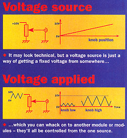 |
A
voltage is just a measure of how much electrical 'push' a circuit has. Plug a voltage
source - like a battery, or synth module - into a circuit and it will push the electricity
around so it starts flowing. The amount of this push - you can think of it as electrical
pressure - is measured in units called Volts.
In an analogue synth, voltages are used to
control how much each module does what it´s designed to do. Turn up the voltages to an
amplifier, for example, and the sound gets louder. Do the same to an oscillator and its
pitch pitch goes up. Try it with a filter and the filter opens.
Modulation sources - low-frequency oscillators,
ADSRs, and so on - are cunningly designed boxes that ramp voltages up and down
automatically in predicted ways. Without them, You and Your friends would have to turn
knobs and dials by hand every time You hit a note. |
Most synths use a standard voltage-control
system. This defines a common one-volt-per-octave scale - in other words, every time the
control voltage goes up by one volt, the frequency of an oscillator doubles. Turn up the voltage by 1/12th of a volt, and the pitch goes up by a
semitone. Consequently, a 4V signal would
cause an oscillator to produce a pitch one octave higher than a 3V signal, and that´s the
theory of one-volt-per-octave.
One fo the clever -and strange- things about
analogue synthesis is that you can interchange control voltage and audio lines, because
there´s no practical difference between the two. An audio signal is just a voltage
that´s wobbling up and down particularly fast, but it´s still basically a voltage, just
like you´ll get from any module.
This means you can use the output of an
oscillator to change the pitch of another, or of a filter, or the gain of a amplifier
(vca). This gives you acces to strange and unusual effects that you can´t create any
other way.
Gate and Trigger
The gate signal told the synth that you had pressed a key. This
voltage, usually in the 5V-10V range, would remain constant as long as the key was held.
As soon as the key was released, the gate signal would stop (drop to OV), and the synth's
envelope would immediately jump to its release stage.
The trigger signal also told the synth you were playing a note, but
unlike a gate, it was a momentary (about 5ms) rather than continuous signal, and could not
tell the synth to produce a sound; it worked in conjunction with the gate. The trigger
signal's purpose was to start the synth's envelope generators, thus articulating the
attack of the note. Whenever the synth received a new trigger, the envelope generators
would be restarted, and the attack of that new note would be articulated. Without a
trigger signal, a new note would sound using the current state of the envelope generator -
much the same as what hoppens in the 'legato' mode found on modern synths.
Triggers came in two varieties. The first, used by ARP instruments,
was a momentary spike where the voltage jumped from OV to 10V then back down to OV. The
other type, called an S-trigger (or switch trigger), was used on Moog synthesizers. It
consisted of a continuous gate-type voltage that dropped to OV when a key was pressed.
This voltage was used to control a switch that produced a trigger when it closed in
response to the voltage drop.
Read more in the modular introduction
Read more in the patching
procedure column
Interactive CV/Gate Basics