DOEPFER
MUSIKELEKTRONIK GMBH
The Trautonium Project

fig. 1
Text by Doepfer Musikelektroniks editorial staff
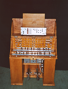
(Fig. 1 shows the Trautonium modell in the Technischen Museum Vienna. We built the electronics for this instrument, i.e. the manual electronics and the sound generation unit. In the upper section the 19 inch frame containing the electronics can be identified. It contains the manual electronics, the prototype of the subharmonic oscillator (A-113) and some modules of the A-100 (VCO, VCAs, Noise, Mixer, Filter) required for the Trautonium sound generation. The mechanics (i.e. the wooden cabinet and the manuals) are built by Hauck Museumtechnik, Hassfurt (Germany).)
The Trautonium is an electronic musical instrument invented by Friedrich Trautwein in the thirties in Berlin, Germany, with enhancements made by Oskar Sala in the fifties which led to the well known Mixtur-Trautonium. The Trautonium can be divided into two logical sub-units: the control unit and the sound generation unit.
1. 1. The Control Unit (Manual)
The control unit of the Trautonium essentially consists of the manual and a foot controller with two associated switches. The Trautonium is modelled on the so-called "Bandmanual" of the Hellertion, invented by Hellberger and Lertes early in this century. But it uses a resistive wire respectively a nonconductive string winded round with a resistive wire (1). The string is stretched in a distance of some cm above a conductive metal plate (2). The isolated terminals (3) of the string are connected to a voltage source of some Volt. A small pressure applied to the string with a finger causes a connection between the string and the plate. As a result a voltage depending upon the position of the finger appears at the plate.
Example: If a voltage of 3V is applied to the string terminals (i.e. left terminal = GND, right terminal = +3V) and the voltage applied to the plate is connected to the control input of a voltage controlled oscillator (VCO, e.g. A-110) one obtains a simple manual that enables to control the frequency of the VCO over about 3 octaves infinitely without steps.

fig. 2
Additionally the plate is mounted movable around an axis (6) with two bearings (5) and can be moved some cm downwards. Two springs (4) mounted below the plate put back the plate into it's neutral position if the pressure is taken away.
The vertical position of the plate is used to control the loudness. In the neutral position the loudness is zero (no sound), in the lowest position the loudness has its maximum. There are different possibilities to obtain this information as a variable voltage (e.g. inductive, capacitive, resistive or opto-electronical sensors).
Example: If the voltage generated by the sensor (range 0...+5V) is connected to the control input of a voltage controlled amplifier (VCA, e.g. A-130, A-131, A-132) one obtains the desired loudness behaviour.
Additionally the total loudness is controlled by a variable foot controller so that 2 serial connected VCAs are necessary to obtain the complete loudness control of the original Trautonium. The first VCA is controlled by the vertical position of the manual, the second by the foot controller.
Above the string a set of about 10...15 metallic spring tongues is mounted on a moveable pole. The tongues are covered by thin leather so that they are non-conductive. The tongues are moveable on the pole and are normally used to define certain musical intervals (e.g. C-E-G-C...) like keys on a keyboard. By moving the complete pole to the left or right the transposition of all tongues is changed simultaneously. The tongues can be used as dummy keys for optical assistance to find the right tones. But they also can be used like real keys, i.e. one presses the tongue with a finger so that the string touches the metal plate and one obtains certain tones (e.g. C-E-G) provided the tongues are adjusted accordingly. The tongues and the pole are not shown in fig. 1 because of clearness. Oskar Sala e.g. uses the tongues for C,D,G and A in each octave.
In the photography showing the Mixtur-Trautonium of Oskar Sala these tongues (8) mounted on the common moveable pole (9) are good to be seen. The other numbers in the photography refer to the same details as in fig. 1 and text above. The bearings and the axis cannot be seen in the photography as they are hidden behind the cover.
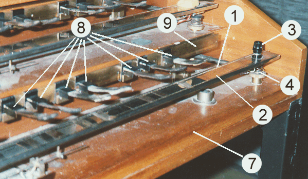
fig. 3
To obtain a manual that can really be used by a musician for virtuoso playing some additional improvements are indispensable, e.g. felt shock-absorber, vibration dampers, light-weight but torsion-free construction, smooth and free-moving ball bearings (5) and much more.
The classical Trautonium (called the Telefunken-Trautonium) had one manual and one foot controller. In the Konzert-Trautonium and Mixtur-Trautonium of Oskar Sala two manuals and two foot controllers exist. Each of the manuals, which are approximately 70 cm (28 inches) long having a range of about 3 ½ octaves.
The foot controllers of the Mixtur-Trautonium are extended by two switches which are controlled by lateral movement selecting 3 different sets of subharmonics (the so-called mixtures, see chapter 1.2) for each of the 2 manuals independently. These switches are good to be seen in the photography below showing one of the foot controllers of Oskar Sala's Mixtur-Trautonium.
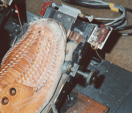
fig. 4
Additionally a special liquid resistor designed by Oskar Sala uses the vertical movement of the manual to control the loudness of the Trautonium. It works as a variable capacitor with glycerine as dielectricum. The adhesion behaviour of the glycerine results in a very specific dynamic control and enables a high resolution in the musically very important pianissimo range.
1.2. The Sound Generation Unit (Subharmonic Oscillator)
The sound generation of the first Trautonium was a sawtooth-like frequency generator. The frequency was controlled by the string manual. The output of the frequency generator was fed into two parallel resonant filters. The footpedal controlled the volume ratio of the output of the two filters. The resulting signal was weighted by the pressure sensor and further fed into a power amplifier connected to a speaker.
The special quality of the Trautonium from todays point of view was introduced by Oskar Sala with the Mixtur-Trautonium. In the Mixtur-Trautonium the frequency of a master oscillator is controlled by the string manual. Four independent frequency dividers generate 4 new frequencies - the so-called subharmonics - from this master frequency. The divisor for each subharmonic can be adjusted between 1 and 24 by four 24-position rotary switches. The subharmonics are a quotient of the master frequency and a integer number in the range of 1..24.
The maximum frequency of the master oscillator in the original Trautonium is about 4 kHz (quotation Sala: highest note C5 = 4186 Hz). As the range of the string manual is about 3 ½ octaves the lowest master frequency is about 400 Hz (quotation Sala: g1 = 392Hz). With the maximum divisor of 24 the lowest subharmonic frequency is about 16 Hz (392Hz : 24).
Each frequency of the 4 subharmonics is always an integer ratio of the master frequency. If you assume e.g. a master frequency of c4 the subharmonics are c3 (c4:2), f2 (c4:3), c2 (c4:4), as1 (c4:5), f1 (c4:6), d1 (c4:7), c1 (c4:8) and so on. These are notes from the minor chord progression c - as -f.
Remark: In contrast to this the harmonics - i.e. the integer multiples of the master frequency - result in the major chord progression c-e-g. The subharmonic progression is the mirror image of the harmonic progression.
A combination of 4 subharmonics is called a mixture. In the Mixtur-Trautonium 3 different mixtures are available for each manual. The 3 mixtures are selected with the lateral operating switches mounted on the left and right side of the foot controller. For each of the 3 positions (left - middle - right) a separate mixture is available. Thus the subharmonic oscillator contains 12 frequency dividers after all.
The term subharmonic should not be taken at face value. The outputs of the frequency dividers are sawtooth-like waves rather than sine waves used in the harmonic theory (Fourier theory). Each of the 4 sawtooth outputs has a strong complete harmonic spectrum as in the sawtooth waveform all even and odd harmonics are present.
Summary: The output signal of the subharmonic generator consists of 4 sawtooth-like waves - the so-called subharmonics. The frequencies of the subharmonics are integer ratios (1..24) derived from a common master frequency. Each subharmonic has a harmonic spectrum (i.e. "real" harmonics) containing all harmonics (even and odd).
The volume ratio between the oscillators is fixed for each of the three lateral pedal positions. In the first Trautonium the sum of the subharmonic signals is fed to two parallel resonant filters. The sound generation unit of the Mixtur-Trautonium contains some more units like noise generator, mixers, envelope generator and frequeny shifter. All these devices already exist as modules of the modular system A-100 and are therefore not described here.
Fig. 5 shows the Mixtur-Trautonium of Mr. Sala. The different function groups are easy to recognize.
In the lower section of the picture the two manuals
1 and 2 can be identified. On the manuals stands a distribution box 3. With this box the control signals coming from the manuals, foot controllers and foot switches can be adjusted and assigned to the sound generation units. E.g. the left sound generation unit (see below) can be controlled with the right or left manual.Above the manual a frame construction with 3 "floors" similiar to the A-100 frame system is located. The two lower floors essentially contain the 2 identical subharmonic oscillators and the related units (Noise, VCAs). One recognizes the 12 two-digit LED displays and the corresponding rotary switches for adjusting the frequency divisors
5. The 12 displays and switches are arranged in 3 columns with 4 rows each. The left column corresponds to the mixture for the left foot position, the middle column for the middle position and the right column for the right position. One below the other the 4 controls for one foot position are located.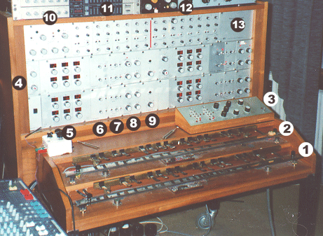
On the left side of each of the frequency divider units the frequency controls for the master oscillator and an auxiliary oscillator (German: Neben-Oszillator)
4are located. The auxiliary oscillator is another sound source and its frequency can be adjusted independent of the master oscillator's frequency so that vibrato or phasing like effects with the typical beat frequency can be obtained.The upper "floor" of the frame construction contains (from the left to the
right):
"Schlagwerk" (10), 4 formant filters for the lower manual (11), 4 formant
filters for the upper manual (12) and the filter distribution unit (13).
The "Schlagwerk" (10) contains two simple A/R envelope generators
(attack/release) that can be used in 2 different modes. In the triggered mode (German:
getriggert) they work like a standard A/R envelope generator and are triggered by the
vertical movement of the corresponding manual. As soon as the manual reaches a certain
position the "Schaltwerk". This works like the Gate signal in the A-100 system.
In the free running mode (German: freilaufend) the envelope generators changes into a LFO
(low frequency oscillator) with adjustable frequency. In this case the position of the
manual has no effect to the "Schlagwerk", i.e. it even triggers no reset in the
free running mode. The control voltages of the 2 "Schlagwerk" units can be used
to control the channel amplifiers. In the triggered mode of the "Schlagwerk"
this is very similar to the VCA control used in most of the analog synthesizers, i.e. an
envelope generator triggered by a Gate controls an VCA.
Each of the 8 formant filters (11,12) consists of a band pass and a low pass. A toggle
switch determines if the filter is used as band pass or low pass. Frequency and resonance
of band pass and low pass can be adjusted independently as well as input and output level.
At higher settings of the level controls even clipping occurs to obtain distortion effects
(German: Trompeten-Effekt, i.e. trumpet-like sound).
The filters are inserted between the channel amplifiers 8
and the summing amplifiers 9. The filter
distribution unit (13) determines the type of connections between the filters and summing
amplifiers. The filter distribution can be set with jumpers on the pc boards behind the
blind panel of the distribution unit. There is no access to the filter distribution during
performance.
The realization of the Trautonium within the A-100 is apparent as the Trautonium-specific units manual and subharmonic oscillator seamless fit to the A-100 idea. A lot of circuits required to complete the Trautonium already exist as A-100 modules - like master oscillator (VCO), filters (VCF), mixers, noise, VCA, envelope generator, frequency shifter and much more. The Trautionium manual can be treated as a new control voltage source (like the MIDI-to-CV interfaces A-190/MCV24/MCV4, Sequencer A-155, Theremin A-178, Light-controlled CV A-179, Foot controlled CV A-177 or others) to control the pitch of VCO A-110/111, sampler A-112 or - of course - the subharmonic generator. On the other hand the subharmonic generator may be treated as a new sound source like VCO, Sampler, Noise or other sound sources. But it is not imperative to control the subharmonic generator from the Trautonium manual. A MIDI-to-CV interface, sequencer, Theremin or any other control voltage source could do this job as well.
The new Trautonium modules should be treated as all the other modules of the A-100. Of course one could built the "original" Trautonium from the new modules. But why should one e.g. not control the subharmonic generator from Theremin, Light or MIDI and modify the sound with a frequency shifter, vocoder and 3 Shepard controlled phasers.
2.1. The Control Unit: Trautonium Manual
This unit is still under development. At the moment we are looking for a company to built the mechanics at a reasonable price. The control electronics is already finished but we have no own mechanical production and so we have to look for a cooperation partner. We will keep you informed at this place about the the state of affairs. But we hope to be able to offer a manual still this millenium.
2.2. The Sound Generation Unit: Subharmonic Generator A-113
The development of the subharmonic generator A-113 is nearly concluded. In the following the momentary state of the development is described (as of August 11, subject to change for the final version).
The design of the A-113 is very close to the subharmonic generator of the Mixtur-Trautonium of Oskar Sala. At this point we would like to thank Oskar Sala and Prof. Hans-Joerg Borowicz, Berlin for the kind assistance during the development of the Trautonium modules.
For the adjustment of the 4 subharmonics, i.e. the 4 divisors for the frequency dividers up/down buttons are used rather than the rotary switches in the original Trautonium. The divisors are displayed with four 2-character LED displays. The adjustment via up/down buttons instead of rotary switches has the advantage that all subharmonic settings can be stored in presets and later edited starting from the values stored in the presets.
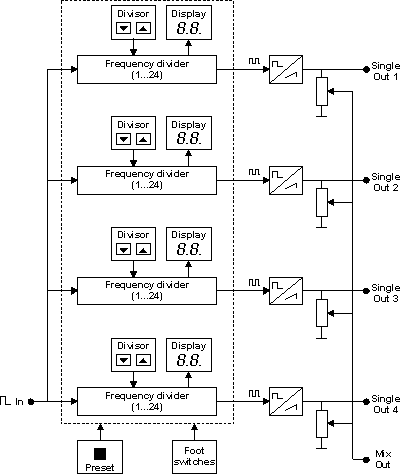
fig. 6
The A-113 features 2 control inputs (Foot Ctr. 1 and 2) to switch between the 3 mixtures for the 3 foot switch positions (left - middle - right) controlled by the switches left and right of the foot controllers. Normally the foot switch signals are connected to these inputs. But the mixture switching could be controlled by any other control source as well (e.g. MIDI controller via MIDI interface or sequencer gate output). The current mixture settings are displayed in the four LED displays. The decimal points of the displays are used to indicate the current foot switch setting resp. mixture selection:
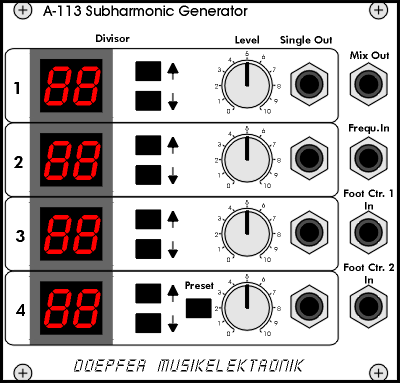
fig. 7
The current mixture setting - i.e. the 4 divisors for left, middle and right foot position - can be stored as a preset. Each preset consists of the 3x4 = 12 divisor values. Probably 99 presets will be available within the module. A new preset is selected with the lower up/down button pair while the preset button right of these is pressed. While this button is pressed the lower display shows the current preset no. (01...99). The upper three displays will be off or probably show "P" or "Pr" to indicate the preset mode. As soon as the preset button is released the normal mode is activated and the current mixture is displayed. If you want to know only the current preset no. you simply have to press the preset button to see the current preset no. at the lower display.
The output waveforms of the A-113 are sawtooth - like the subharmonic oscillator of the original Trautonium. The four waveforms are available as four single outputs as well as a mixed output with adjustable level for each of the subharmonics. The master oscillator is not an integral part of the A-113. Instead of this the module has an input for an external master oscillator. Normally the rectangle output of a VCO (e.g. A-110) is connected to this input. The frequency divider/sawtooth converter of the A-113 use the same range as the original Trautonium i.e. about 20Hz...5kHz.

fig. 8
The above picture shows the Trautonium electronics built for the Technische Museum Vienna. It contains the prototype of the subharmonic oscillator (A-113) and some A-100 modules (VCO, VCA, Noise, Mixer, Filter) required for the Trautonium sound generation.
On the left there are two 1/4" stereo jack sockets for connections to the manual (string and manual position sensor). The manual electronics is located behind the jack sockets. Right from the sockets follow the master oscillator (modified A-110, only octave rotary switch and tune control are available) and the subharmonic oscillator with the four 2-digit displays. In this prototype the preset feature and the mixture switching with the foot switches is still missing. Right from the subharmonic oscillator the auxiliary oscillator (A-110), Noise (A-118), Mixer (A-138b), 2 Filters (2 x A-121) and VCA (A-131) are located. These modules are a little bit modified (no jack sockets and not all controls available) and internally connected (no external patches). At the left side of the panel the audio output is located.
The Trautonium model of the Technische Museum Vienna can be played with some restrictions mentioned above (e.g. no foot controls). But the mechanics of the manuals still has to be improved as the available prototype does not yet meet the standards of a playable musical instrument especially with regard to smoothness, repetition, mechanical noise, damping and much more.
The A-113 will probably be available in fall 1999. The date for the availability of the manual is uncertain as the mechanical problems described above have to be solved. We will keep you informed here about the the state of affairs. All specifications, prices and dates of availability are without obligation, not binding and still subject to change.