| Module |
Description |
Controls &
Ins/Outs |
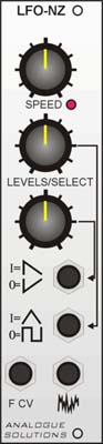 |
LFO-NZ VC-LFO / Noise
INTRODUCTION:
An LFO module with 2 separate waveform outputs out of a choice of 4.
Use an LFO to control a VCO (to create vibrato), a VCA (for tremelo)
or to control a filter's cut-off frequencer (wah-wah /filter sweep).
Use it any where you want to change a module's performance over time.
SPEED:
This sets the LFO frequency
RAMP / REVERSE RAMP LEVEL / SELECT SWITCH:
Sets the output level to the Ramp out jack of the Ramp signal. Pull the
control out to select Reverse Ramp.
TRIANGLE / SQUARE LEVEL / SELECT SWITCH:
Sets the output level to the Triangle out jack of the Trianlge signal. Pull
the control out to select Square |
| Inputs: |
Outputs: |
LFO Controls: |
Frequency
CV |
Ramp/
Reverse
Ramp
Triangle/
Square
Noise |
Speed
Ramp/
Rev.Ramp
Level
Tri/Sqr
Level
|
| Switches: |
Power: |
Indicators: |
Push/Pull
switches
built into
level pots
select which
waveform is
affected by
the level
control and
is output at
socket.
|
+/- 12V
Size:6HP
|
LFO Frequency
|
|
Controls
S+H Lag
This adds slew (or portamento) between each changing voltage held by the S+H.
Noise Level
Alters the noise level.
LFO Waveform
Selects the waveform that is fed through the Delay circuits:
S+H (Sample and Hold) , Noise, Sawtooth, Reverse Sawtooth,
Square, Triangle, Sinewave.
LFO Freq
Sets the frequency of the LFO.
Range
Coarse setting for the LFO frequency. Shifts the range of the Freq pot in 3 steps.
LFO Delay
Alters the LFO delay time. Note, for this function to work, a trigger must be fed into the
DEL TRIG socket.
LFO Level
Sets the final output level of the delayed LFO signal.
Sockets
S+H In
This is the signal source for the S+H. Normally the noise output would be used for a
randon output.
S+H Clock In
Each clock or gate pulse will make the S+H sample the input signal then hold it till the
next clock signal. Normally a square wave signal would be fed into here, like the LFO1
square wave output.
S+H Sig Out
This is the output from the S+H unit. This is also fed into the S+H posisition on the LFO
Waveform switch.
Noise Out
This is an audio output from the noise generator. This can be fed into the S+H signal
input for random S+H.
LFO Reset (RST) In
When a positive voltage is fed in here, the LFO waveform will reset, so it will restart
its waveform cycle from zero.
LFO Delay Trigger (DEL TRIG) In
When a positive voltage is fed in here, it will activate the the delay feature, so the LFO
signal coming out of the DEL socket will be delayed for a period set by the DELAY pot.
LFO Frequency CV (FCV) In
A 0-10V control voltage can be fed in here to control the LFO frequency
LFO Delay (DEL) Out
The delayed LFO signal is output here.
LFO Waveform Outs (triangle, reverse saw, saw, square)
The direct and individual waveforms are output at the sockets.
The Low Frequency Oscillator (LFO) In More Detail
The LFO gives a control voltage in the shape of a waveform.
It is basically an oscillator which generates a cyclic waveform at low frequencie below
the audio range.
The LFO can produce different waveshapes used to modulate
various other modules. Common uses of LFO modulation are to obtain vibrator (by modulating
the pitch of a VCO), wah-wah (by modulating the filter cut-off frequency), tremelo (by
modulating the gain of a VCA).
Some LFOs can have there frequency voltage controlled like
with a VCO. Some have a reset input. When a gate or trigger signal is received at the
reset input, the LFO waveform will be reset to zero, re-starting its wave cycle. Rarely
found on LFO modules is a Delay time setting in conjunction with a Delay trigger input.
The Delay adjusts the rate it takes the LFO signal to go from zero to full intensisty,
initiated by a gate or trigger signal at the Delay trigger input.
Modulation is the most vital consideration when using the
synthesiser as an electronic musical instrument. Why? Sound is not music, merely a carrier
of information. It is the change in sound that our ears perceive as music; our
brains, via our ears, are good at detecting and assessing these changes and thus sound is
merely the carrier of musical concepts.
Modulation is the business of making changes to the
constituent elements of sound, so really if we are to accept the above paragraph music and
modulation sources go hand in hand. Below we will go into detail of the major modulation
source in an electronic music synthesiser - the low frequency oscillator.
Low frequency oscillations are defined as periodic
vibrations at frequencies below the audio threshold. You will all be aware of the
fundamental ideas behind oscillators and voltage control. The LFO cannot act as a sound
source, it is a modifying element that is used to process and control other elements of
the sound. The ‘low’ in LFO defines the oscillator as operating at frequencies
below the audio threshold, which for most of us is around 30Hz.
If we examine the LFO in its simplest block diagram format,
below, it can be seen that it is a source signal, i.e. the LFO is not reliant on any other
input such as CVs or triggers; it produces a periodically varying output CV that is purely
a function of the front panel LFO rate control. This isn’t always the case, though,
as there are some more advanced LFOs that can be controlled themselves.
But to continue with our simple LFO, it is generally the
case that it will provide triangle and sqaure wave output signals at rates between 0.01 up
to about 30Hz. In some cases you will find that the LFO produces sine instead of triangle
waveforms - this is in fact preferable, but it was the case that manufacturers found it
more expensive to incorporate sine wave generators into their instruments and consequently
we often have to make do with the sharp edges of the triangle wave. This isn’t too
horrific a proposition,as one has to listen quite closely to the modulated signal to
detect its nature, however of course, in the audio spectrum the difference brought about
by the higher harmonic content is considerably more noticeable.
In the more eleborate LFOs a wide range of additional
waveform outputs and features are provided - ramp andpulse in particular.
The Role of the LFO
The most common use for the LFO is pitch or frequency
modulation. Sine or triangle wave modulation of the VCOs is known as vibrato, square wave
modulation as trill. Gernerally frequency modulation applied via the modulation
performance controls (wheels, ribbons, joysticks or whatever), however it is possible to
permanently route the LFO to the VCO if it is so desired, though the effect is generally
rather monotonous for musical apllications.
Vibrato is generally applied so that the pitch deviatioon
is less than plus or minus a semitone, applied around the initial frequency of the
oscillator, the overall modulated sound output retains its original tuning.
However trill is the oscillation between two steady
frequencies. The square wave oscillates between a zero volt level (which has no effect on
the pitch of the VCO) and a positive value, which determines the upper note to which the
trill is set.
The other use of the LFO in conjuntion with the VCO is to
provide a control signal with which to modulate thepulse width.
Sine or triangle modulation of the filter goes by various
names, the most common and unlikely being that of ‘growl’, though sometimes the
terms ‘wow’ or ‘wow-wow’ appear. LFO modulation of the filter is less
commonly utilised, as musically it is not as important as vibrato or trill; however, iti
is often useful when routing the LFO to the oscillators, to parallel the signal to the
filters in order to enhance the effect.
LFO modulation of the VCA usually employs either sine or
triangle wave for tremelo effects or the ramp down waveform which can be used for
similated echo effects.