| Module |
Controls & Ins/Outs |
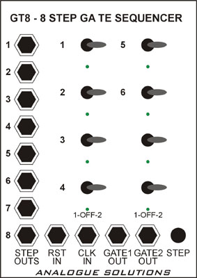 |
GT8 8 Step
Dual Gate Sequencer
Inputs:
Reset In
Clock In
Outputs:
2 x Gate Range 0/5V
8 x Step Outs (on=5V)
Power:
+/-12V, +5V
Controls:
8 x Gate switches
(left=channel 1, middle=off, right=channel 2)
Indicators:
8x Step LED's
Size:
18HP |
Introduction
As they are single channel completely independent
sequencers, they can be bought as and when they are needed, they can be clock at different
clock divide ratios, they can each have different step lengths. None of these features are
available with multi-channel sequencers.
These sequencers have a step out socket for each step
(mainly for use with adjusting sequence length. Other sequencers use switches to change
length). The advantage is that the sockets need not only be used for changing sequence
length, but they can be used individually to clock or trigger other devices. The 8 step
outs are basically the same as a Doepfer A161 trigger sequencer module making the CV8 and
GT8 exceptional value.
When used with the master clock module MC01, all sequencers
can be reset globally from the Master Clock and they will be reset to THE LAST STEP. With
just about all other sequencers, especially when using MIDI as the master clock, the
sequencer must manually be stepped to the last step, otherwise when the clock is started,
step 2 is in fact the first step triggered. Our automatically go to the last step
eliminating this problem (see note in MC01 section for more explanation).
Main Applications
For triggering envelopes, clocking other devices, or
controlling CV's. The GT8 comes with a 5V range as standard. This range is ideal for
triggering most monosynths and envelopes.
If requested when ordering, the CV8 can be given a 10V
range. It is possible to change to range between 5 and 10V by adding or removing resistor
R13 (100K) on the main board. Having this resistor in place makes the range 10V. Changing
this yourself is safe to do but will invalidate the warranty.
Controls In Detail - standard operation.
Clock In:
The GT8 requires a +5V clock signal. Each clock signal will
advance the sequencer 1 step. When the last step is reached, it resets back to the first
step. Take the clock signal from an LFO, Clock module or MIDI to Clock converter.
Step Outs:
There are 8 step out sockets. As each step 1 to 8 is
reached, the corresponding step out socket will go high (output +5V). By patching one of
these outputs into the Reset In socket, the sequence length can be altered between 1 to 7
steps long. For example, to obtain a five step sequencer, patch the next number up step
output into the reset input, i.e. step out 6. To have an eight step sequencer, no reset
patch is needed.
Gate 1/2 Outs:
Either of these two sockets will output a +5V gate when at
a particular step, the corresponding switch is in either position Gate 1 or Gate 2. Centre
position will result in not Gate from either socket.
The pulse width of the clock input decides the pulse width
of the Gate outputs.
Step Button:
This allows the sequencer to be manually stepped by step at
a time whilst the clock is not running. It can also be used to reset the sequence. As with
most analogue sequencers, step it to the last step (8 or whatever is patched) so that when
you start the clock, the sequencer starts on position 1.
Note: The step button will only work when any clock input
signal is at a low state (0V). So it will note work when the clock input is high. This
situation will note arise in normal use, as one would only normally use the step button
when the master clock is stopped (making the clock signal low). If the sequencer is being
clocked by a clock divider, even when the clock is stopped, it is possible that the clock
signal may still be high until reseted.
Gate Switches:
There are 8 Gate Switches, 1 for each step. They have three
positions. When switched left, Gate 1 is active, right, Gate 2 is active, and centre is no
Gate. The voltage range is 0 to 5V.
LED Indicators:
There are 8 LED's. These will light in turn to show step
position.
Alternative Applications Of Controls:
Clock In:
The sequencer does not have to be stepped through at normal
regular intervals as is usual. It can be clocked from any source, such as the gate from a
MIDI-CV converter or monosynth, the trigger out of a drum machine such as the TR606/808,
or from the gate outputs of other analogue sequencers. This allows it to step through the
sequencer rhythmically, as and when you want.
Reset In:
The reset signal does not need to be taken from the step
outputs. It can be taken from an source, such as Gates from MIDI to CV converters, synth's
or other analogue sequencers.
Step Outs:
These can be used individually to clock other analogue
sequencers, to trigger analogue percussion modules, gate monosynths, or control analogue
switching modules such as the Fill In Module.
Each step out is basically a divide by 8 clock divide
(relative to the clock input signal). Any step output (normally one) can be used to clock
something else 8x slower.
More GT8 Example Patching
Any step out is a divide by 8 clock divider.
Take step 1 (or any other step output) into the clock of
another sequencer.
GT8 controlling open and closed hihats (or 2 monosynths);
Gate out 1 to CH, Gate out 2 to OH.
Use a pulse shaper on the clock input of the GT8 to change
the Gate output pulse widths.
Take different step outputs (from same or other CV/GT8
sequencers) and mix them with a multiple to get another gate sequencer.
When using a clock other than the MC01 master clock module,
(as with all analogue sequencers), you must manually step to the last step of the sequence
before you start the clock. This is done automatically when using the MC01.
Using a CV8, GT8 & MC01;
Run one at 1:1 clock ratio, and the other at a divided down
clock ratio, say 1:4 for interesting effects.