A-100 Construction details
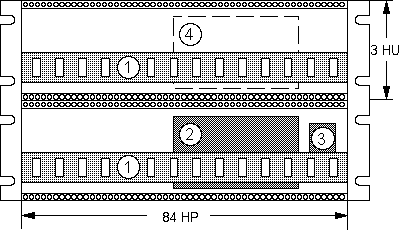
The A-100 modular system is based on a standard 19" rack system into which individual modules can be fitted in any chosen layout. The standard 6HU rack system conforms to the 19" standard, and consists of two sections each 3U high, tied together by 6U side panels. It contains two system busses (1), the internal power supply (2) , and the main electrical supply socket (3). A small 3HU rack is available too.

Fig.1
Module front panels are all 3U high. Their width is measured in HP (1 HP = 5.08 mm or 1/5"). The rack system has a usable width of 84 HP (= 426.4 mm). If the modules you install don’t use up the entire 84 HP, then you must cover up the spaces with blanking panels. In the description for each module (e.g. A-110) you will find the width of the module in HP measures.
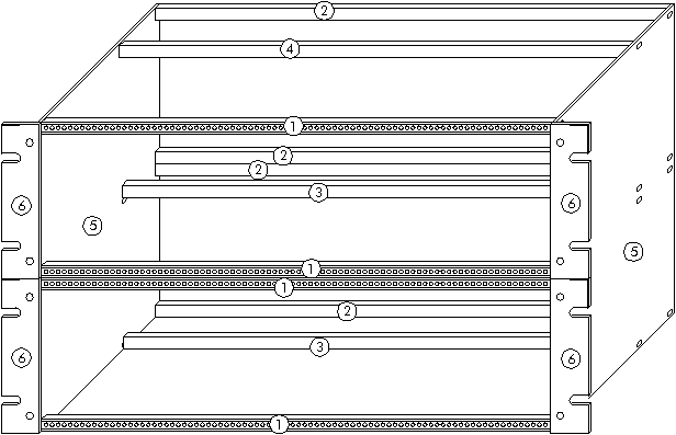
Rack system construction details:

Fig.2
In detail the 6HU rack system is made of the following
components:
(1) front rail version 1 (with lip), with threaded inserts (for module mounting)
(2) front rail version 1 (with lip), with slide nuts (for rear covers mounting)
(3) front rail version 2 (without lip), with slide nuts (for bus board mounting)
(4) front rail version 2 (without lip), for increasing stability only
(5) side plate
(6) 19" mounting flange
In each 6HU rack system there are two system bus bars (one for each section), to each of which up to 14 modules can be connected, using ribbon cable. The bus bar serves to supply power to the modules, and also to send control voltages etc. to some of the modules.
The standard rack system power supply produces voltages of +12 V and -12 V and can put out a maximum current of 650 mA. In setting up a modular system, make sure that the total current required by all the modules doesn’t exceed this maximum. If it does, then a second power supply (see Accessories) will need to be installed (at position (4) fig.1). As a rule, though, one power supply should be sufficient for a rack system. Alternatively a +5V power supply may be installed at position 4 (fig.1) if a +5V power supply is required and the +5V low cost adapter is not sufficient (e.g. if many MIDI interfaces are installed). You will find a remark at the module description if the module requires +5V.
Installing modules
Important: Before you install a module into the rack system:
D Calculate the
total current requirement of existing modules plus the new module/s
D Check
that this total is less than 650 mA
D If it is,
the existing power supply is fine
D But if the total
current requirement is more than 650 mA, you must install a second power supply
before installing the module/s. Follow the installation notes that come with the second
power supply.
Ignoring this warning can result in damage to your system, and will void your guarantee!
Once you’ve checked that there is sufficient current in reserve for the extra module/s, there’s nothing to stop you going ahead and installing them. Read on!
First of all, take the A-100’s plug out of the wall socket.
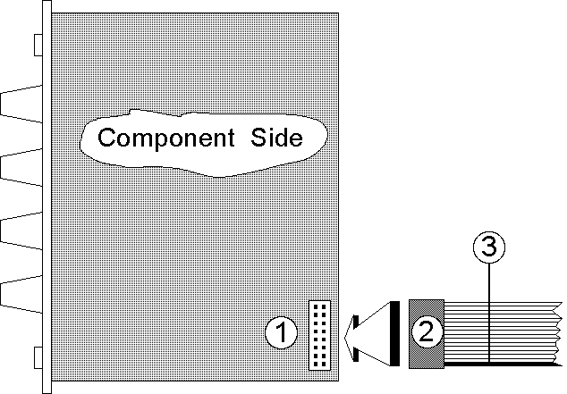
Plug the supplied ribbon cable into the module’s bus socket (see (1) in Fig. 3). As a rule, the cable is 16-way, but some modules only have a 10-way cable. Look carefully at the cable, and then press the appropriate connector onto the module’s bus pins (see (2) in Fig. 3).

Fig.3: Connection the module to the bus connector
Check very carefully that it is connected so that the coloured marking on the ribbon cable is at the bottom of the module’s connector (see (3) in fig. 3), and that the connection is perfect, and pushed fully home, not at a slight angle. Failure to check this may result in the module’s instant destruction as soon as the power is turned back on.

Fig. 4: Connecting the module's ribbon cable to the bus board
Now join the free end of the ribbon cable (see (2) in fig. 4) to the nearest available position on the system bus board (see (1) in fig. 4).
Check very carefully that it is connected so that the coloured marking on the ribbon cable is at the bottom of the bus connector (see (3) in Fig. 4), and it is pushed fully home, not at a slight angle. Failure to check this may result in the module’s instant destruction as soon as the power is turned back on!
When you’re installing extra modules, it may be
necessary to take another module or two out, to allow you easier access to the bus board.
Place the module carefully into the space in the rack, and fasten it firmly in place with
the supplied screws. Put back any covers or blanking plates, and screw them in firmly.Now
plug the system A-100 back into the main power supply, and switch it on.
Test out the newly installed module.
If it doesn’t seem to be working as expected, immediately disconnect the
system from the power supply again.
In this case, double-check the connections, making completely sure that the ribbon cable
is the right way round where it connects to the module and the bus.
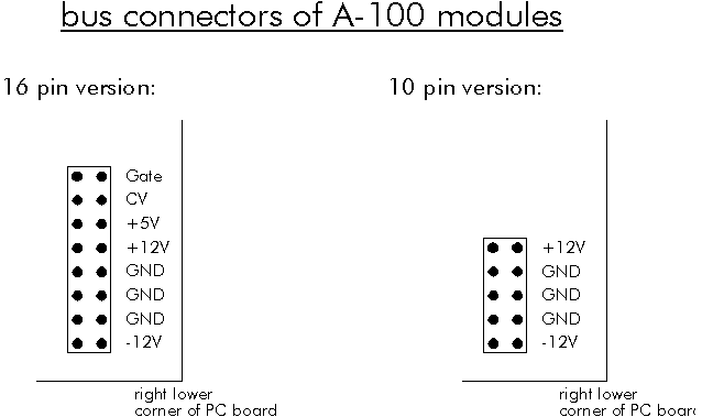
If you want to run single A-100 modules without using our bus board, power supply and frames here is the pin-out for module's bus connectors.

Fig. 5: Pin out of the module's power supply connectors
Pay attention that applying other than the described voltages may result in the module’s instant destruction !
Interconnecting modules
For connecting modules to each other, you need mono mini-jack (Æ 3.5 mm) patch leads.