A-129 Vocoder Subsystem

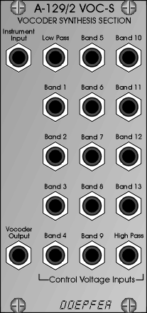
Like a ring modulator, the vocoder needs two input signals: a speech element which serves as the raw material for the tonal shaping, and is patched into the analysis section; and a carrier signal, which is patched via the instrument input into the synthesis section.
The speech signal is chopped up and analysed in the A-129/1 module, and then combined with the carrier signal in the A-129/2 synthesis section. As a result of this procedure, the carrier signal assumes the tonal character of the speech signal, but with its own pitch maintained.
Since the A-129 is a modular vocoder, and the connections between the analysis and synthesis section are external, using patch-leads, you can use this interface to patch in your choice of modules (eg. attenuator, slew limiter, CV-to-MIDI / MIDI-to-CV interfaces,, inverter, etc.).
The A-129 /2 synthesis section can also be used as a stand-alone voltage-controlled filter bank - or in combination with a MIDI-to-CV interface as a MIDI-controlled filter bank.
For more detailed information please look at the English A-110
user's guide alternatively as html
file (for browser view) or as pdf
file (for printout).
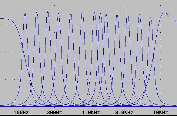
Filterplots of the 15 filters used in the A-129/1 and -2


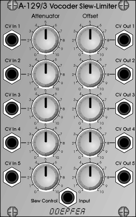
Using the A-129 /3 just on its own, two functions are available:
Attenuator: whatever signal is patched into the CV input can be attenuated by your chosen amount before being sent to the CV output. The attenuation is set with a control knob.
Offset Generator: whatever signal is patched into the CV input will have an offset voltage added to it before being sent to the output. The offset is variable with a control knob.
To use the Slew Limiter section of the 129 /3, you need to have module A-129 /4 (Slew Limiter Controller) as well. It has several dedicated functions, and gives you control over the following slew limiter functions:
- Manual control of the slew rate
- CV control of the slew rate, with an input attenuator
- Choice of three functions: "Follow", "Slew" and "Freeze"
- Freezing the output voltages for the duration of a gate
This set of functions is operated by the Slew Limiter Controller, A-129 /4.
Usually, the slew limiter is patched between the CV outputs of the analysis section and the CV inputs of the synthesis section (see chapter 5, User examples).
You can also use module A-129 /3, particularly in combination with A-129 /4, for other purposes. For example, using the A-129 /2 synthesis section, you can make a filterbank.
There's also the possibility of connecting the frequency bands of the analysis and synthesis sections arbitrarily, so that, for instance, a low frequency band in the speech signal can control a high frequency band in the carrier signal.
For more detailed information please look at the English A-110 user's guide
alternatively as html file (for
browser view) or as pdf file
(for printout).
 |
The Voiced /
unvoiced detector (A-129 /5) can recognise voiced and unvoiced sections in the speech
signal, and switch the carrier signal accordingly. The incoming speech signal is processed
through a pre-amplifier with adjustable gain and a treble boost unit. The treble boost
improves the vocoder effect. The voiced/unvoiced recognition system controls a voltage
controlled switch (like A-150) which is used to switch between the voiced and unvoiced
carrier signal (e.g. VCO and Noise). Additionally the voiced/unvoiced information is
available a a gate signal. A LED displays the unvoiced state. For more detailed information please look at the English A-110 user's guide
alternatively as html file (for
browser view) or as pdf file
(for printout). |
A special MIDI-interface A-195 for the vocoder system is
planned. The basic functions are a 16-way CV-to-MIDI interface and a 16-way MIDI-to-CV
interface (way 16 will be used for other functions like controlling slew-rate or
voiced/unvoiced). The CV-to-MIDI section converts the CV outputs of vocoder analysis into
MIDI controllers which may be recorded by a computer sequencer. The MIDI-to-CV section
converts incoming MIDI controller information into CV's for the vocoder synthesis section.
Additionally we plan to store some factory and user definable 'vocals' in the MIDI
interface so that you may call up complete vocals (like 'a', 'e', 'o', 's', 'sh' and so
on) by MIDI program change events (may be we use another MIDI event type for this
purpose). Thus the vocoder system will become a universal MIDI controlled filter system
not limited to the standard vocoder features.
Module |
Width |
Current |
|---|---|---|
A-129/1+2 |
32HP |
160mA |
A-129/3 |
16HP |
40mA |
A-129/4 |
8HP |
30mA |
A-129/5 |
8HP |
30mA |